1.1 History of Optical Fiber:
Optical Fiber focuses studies light propagation in transparent dielectric waveguides. Fiber optics are used to transport data from one location to another. The most common usage of fiber optics nowadays is as a conduit between terrestrial hardwired devices.
Conventional systems were unable to handle the volume and pace of data transmission because of the constraints of the carrier frequencies. It is better to have more bandwidth and information-carrying capacity available than to have less of either.
Those in their First generation
For the first time, GaAs semiconductor lasers were used in the first generation of light-wave systems.The following are some of the other characteristics of this model generation:
i) The bit rate is 45 megabits per second.
ii) The repeater spacing is set to a maximum of 10 kilometers.
Those in their second generation
i) The bit rate ranges from 100 Mb/s to 1.7 Gb/s.
ii) Repeater spacing is set at 50 kilometers.
iii)The operation wavelength: 1.3 µm
iv) the semiconductor, In GaAsP
Those in their Third Generation
i) 10 Gbps (Gigabits per second)
ii) A repeater spacing of 100 kilometers
iii) 1.55 m is the operating wavelength.
Those in their fourth generation
The WDM approach is used in the fourth generation.
i) The bit rate is 10 terabytes per second.
(ii) Repeater spacing: greater than 10,000 km
iii) The operational wavelength ranges from 1.45 µm to 1.62 µm.
Those in the fifth generation
For the fifth generation, it employs Roman amplification methods and optical solutions.
i) A bit rate ranging from 40 to 160 Gb/s.
ii) repeater spacing ranging from 24,000 km to 35,000 km
iii) Its operating wavelength ranges from 1.53 to 1.57 µm.
1.2 General Optical Fiber Communication System
The following key elements make up the basic block diagram of an optical fiber communication system:
- Transmitter
- Information channel
- Receiver
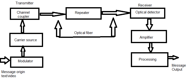
Message origin: A transducer converts a non-electrical message into an electrical signal. Sound waves are converted into currents by microphones, and pictures are converted into currents by video (TV) cameras. The message has already been converted to an electrical signal for delivery via computer.
The modulator serves two main purposes:
- It formats the electrical message.
- It imprints this signal into the carrier source’s wave.
Analog and digital modulation are utilized.
Carrier source: The wave that transports data is generated by the carrier source. This wave is called the carrier. A fiber optic system uses a laser diode or a light emitting diode. For long distance propagation, they are termed optic oscillators.
Channel coupler: The information channel receives power from the coupler. The channel coupler is a lens in an atmospheric optic system that collimates the source’s light and directs it towards the receiver. The modulated light beam must be efficiently transmitted to the fiber via the coupler. Due to significant losses in fiber networks, channel coupler design is critical.
Information channel: This channel links the transmitter and receiver. Optical fibers have a channel that is made up of a glass or plastic fiber. There should be little attenuation in the information channel, and a wide light acceptance cone angle. Optical amplifiers amplify weak signals. Long-distance communications need amplifiers to power the receiver. Only digital systems may employ repeaters. In order to transmit weak and distorted optical impulses, they transform them to electrical signals.
The propagation period of the waves moving down the information route is also significant. A signal going via a fiber is usually separated into rays and contains multiple optical frequencies. The signal is distorted as a result of this. The pulses in digital systems spread and distort. Because of the excessive spreading, successive pulses begin to overlap and lose their individual character.
Optical detector: The data being sent is detector. This is done via a photodetector in a fiber system. The detector’s current is proportional to the power of the incident optical wave. The detector output current includes the data. Filtering and amplifying the detector output removes continuous bias.
Photodetectors are small, inexpensive, have a long life, use little power, have high sensitivity to optical signals, and respond quickly to changes in optical power.
Signal processing: Signal processing comprises filtering and amplification. Filtering optimizes signal to noise ratio. A digital system block is a decision circuit. Quality communications need a low bit error rate (BER).
Message output: The signal processor converts the message’s electrical form into a sound wave or visual representation. When computers or other machinery are linked by fiber, these signals may be used immediately.
1.3 Need of fiber optic communication
In recent years, fiber-optic transmission has emerged as the most important means of communication. [10] Because of the following conditions, it differs from the usual system:
A low-loss transmission medium is necessary for long-distance transmission systems.
It is necessary to use small and light-weight transmitters and receivers.
The transmission span must be increased.
A product with a higher bit rate-distance is required.
Because a fiber optic communication system meets these conditions, it is generally accepted.
1.4 Optical Fiber Communication System Advantages
Wide frequency ranges: The light-wave has a frequency range of 2×10¹² Hz to 3.7×10¹² Hz. As a result, fiber optic cables have a substantially larger information-carrying capacity. [11]
Extended range low signal attenuation: Attenuation in fiber optic cables is considerably low compared to copper wires. It is usually less than 1 dB/km. Thus, the repeaters may be placed farther apart.
Cross-talk resistance: Fiber optic cables are very resistant to electrical and magnetic forces. Fiber optic cables do not create a magnetic field since they are non-conductors of electricity. As a consequence, there is no cross-talk between the fiber optic lines when using magnetic induction.
Electrical noise sources such as lighting, electric motors, and fluorescent lights create conductive and radiative interference that fiber optic cables are resistant to.
Fiber cables are substantially lighter than copper or aluminum wires since they are constructed of silica glass or plastic. Transporting lightweight fiber cables is less expensive.
Due to its compact size: Because of its tiny fiber diameter, the file cable consumes less storage space than conventional cables. Because fiber cables are more durable and sturdy, they can carry a greater load. Because fiber optic cables are more durable and sturdy, they can carry a greater load. It is safer to use fiber-optic cables than other types of cabling. Because fiber cables do not emit a signal, tapping into one is almost impossible. These fibers are more secure due to the absence of ground loops.
Long-distance transmission: Lower attenuation means that transmission over longer distances is possible. As a result, fiber cables are more suited to coping with adverse weather conditions than copper lines. There is no limit to the temperatures that they can operate at. They are unaffected by corrosive liquids or gases.
Fiber cables are safer and simpler to install and maintain than copper lines. They are non-conductors, so there are no shock concerns since they don’t have any current or voltage.
Because of their small size and light weight, they are easy to install. The cost of a fiber optic system is lower than that of any other technology.
1.5 Optical Fiber Communication System Disadvantages
Expensive initial cost: The initial cost of installation or set up is extremely significant when compared to other systems.
Costs of maintenance and repairs: Fiber optic network maintenance and repair is not only complex but also costly. Because optical fibers are so little, connecting and testing them is a breeze. Fiber joining is a time-consuming and costly process that requires the employment of specialized expertise.
Tensile stress: Optical fibers are more susceptible to buckling, bending, and tensile stress than copper cables. As a consequence, optical fiber technology is confined to a few connections to copper cables for premises and floor backbones.
Short links: Even if optical fiber cables were available, the high cost of optoelectronic transducers would make replacing every small conventional connection (e.g., between computers and peripherals) uneconomical.
Fiber losses: influence the amount of optical fiber available to the photodetector at the end of the fiber length due to scattering, dispersion, attenuation, and reflections.
1.6 Optical Fiber Communications: Applications
Fiber optic cables have a broad range of applications and industries. Among the many applications for fiber optic cables are the following:
Medical: Surgical lasers, imaging devices, and light guides are all examples of their many use.
Defense/Government: Seismic and SONAR hydrophones, aircraft wire, submarine wiring, and other vehicle wiring, as well as field networking.
Telecommunications: fiber is installed and utilized for sending and receiving data.
Networking: It is used to link users and servers in a variety of network scenarios to improve data transmission speed and accuracy.
Commercial or industrial: used for imaging in hard-to-reach areas, EMI wiring, temperature, pressure, and other measuring sensors, and wiring in automobiles and industrial applications.
Broadcast/CATV: In order to link CATV, HDTV, the internet, and other applications such as video on demand, broadcast and cable companies need fiber optic lines. Fiber optic cables are utilized for lighting and imaging, as well as for measuring and monitoring a wide range of factors. Fiber optic cables are also employed in research and development as well as testing in all of the sectors indicated above.
Md. Abdul Kayum
Instructor